The goal of this project was to construct a low-cost expandable robot platform
that Aurorans members can build on without a lot of hardware.
Danny and I reckoned
that most technology enthusiasts would have a laptop and using a laptop gives
the advantage of a familiar environment for for use and development of the
software for the robot. Besides the laptop and some standard rechargeable
batteries the components required for version 1 are:
I had an old Dell M40 laptop lying around that I was not doing anything with
so although it’s a little old and underpowered it makes a reasonable choice as
a controller (large display, networking, USB, speakers etc). It’s main
disadvantage is that it’s large and heavy and only has 256Mb of RAM. I wanted
to build something that placed the laptop a reasonable height off the ground
to make it easier for people to interact with - luckily I had the frame of an
old steel chair lying around - much to my wife’s despair I do tend follow in
my Dad’s footsteps and keep stuff thinking “it will come in useful one day”
which provides the required and and some scraps of laminated chipboard for the
chassis and laptop mount.
Chipboard is not my first choice of material since it’s quite heavy relative
to its strength but the local Homebase failed utterly to provide anything more
useful (was hoping for some thick plywood but would have had to buy a 8’x4’
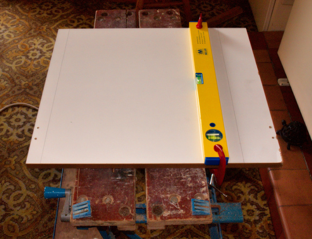
sheet when I only wanted a 42cm square piece. Since chipboard is too weak for
me to rely on woodscrews to attach the hardware I was forced to drill through-
holes and bolt everything to the chassis as shown below.
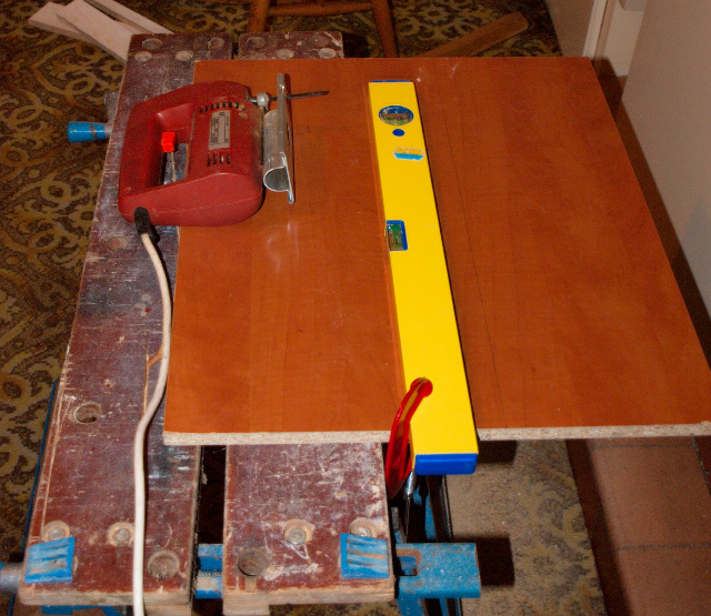
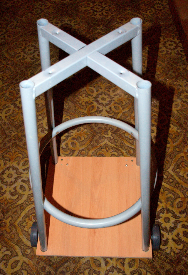
Here’s the chipboard for the top and bottom and the remains of the dismantled
chair that will raise the platform off the ground.
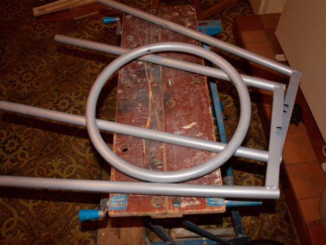
Here the chair frame has been re-assembled and placed on the cut-to-size
chassis to check dimensions.
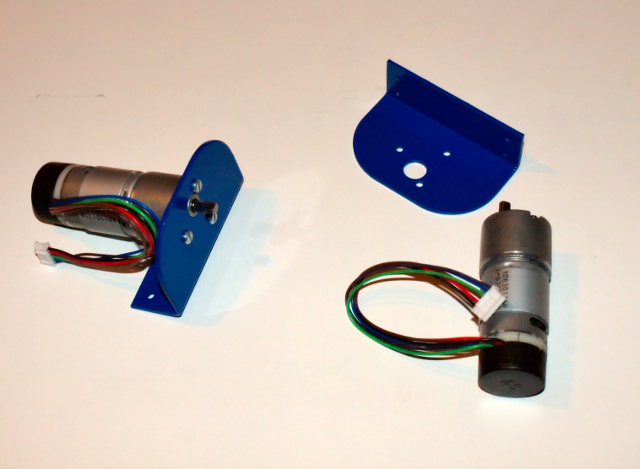
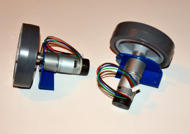
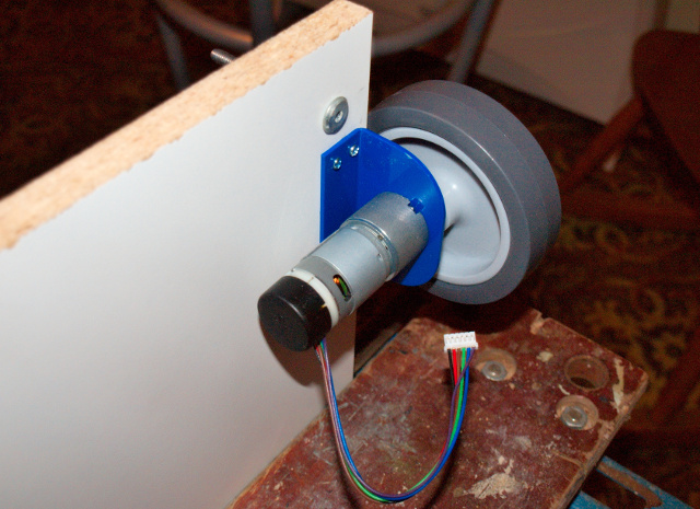
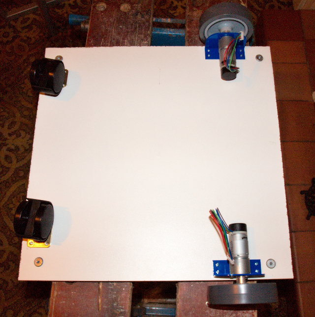
Here are the motors, wheels and mounts from the RD02 drive system
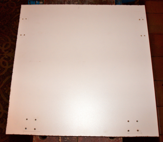
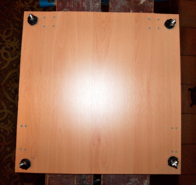
The underside of the chassis with the bolt holes for the motor mounting
brackets and castors drilled.
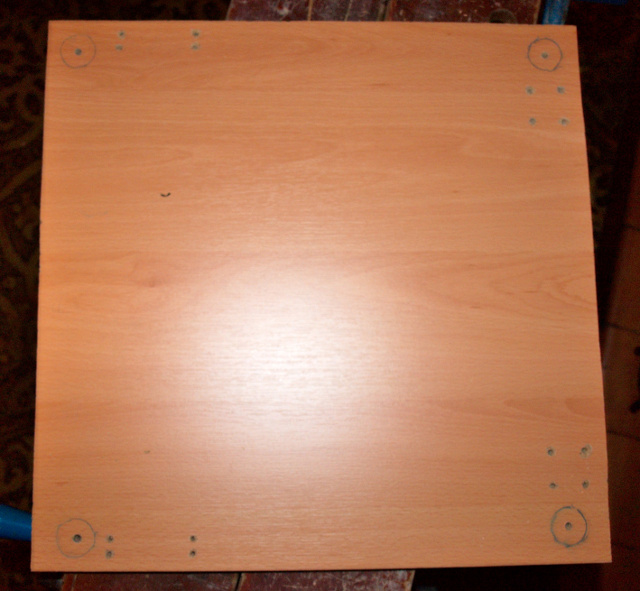
The upper side of the chassis with the positions of the chair legs marked.
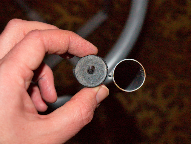
I decided to attach the chair legs to the chassis by putting bolts (saved from
when we dismantled our daughter’s cot when she became old enough for a proper
bed) through the chair feet. This method is simple but has the disadvantage
that the chair is only held to the chassis by the friction between the plastic
feed and interior of the chair leg - fortunately this seems to be sufficient
as long as the robot is not lifted by its top for too long.
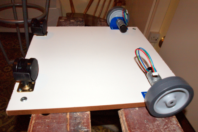
The motors and castors attached to the chassis.
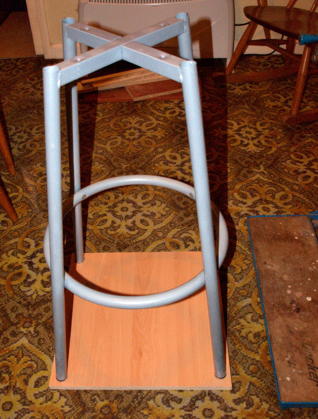
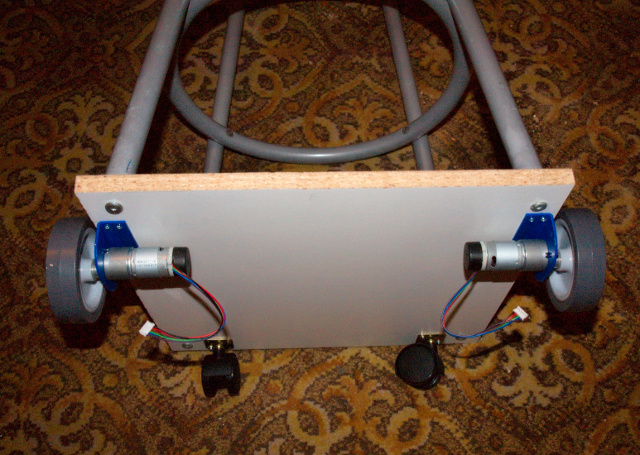
The chair frame attached to the completed chassis.
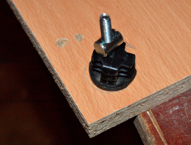
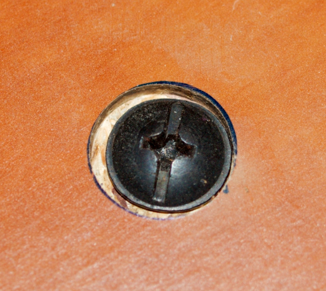
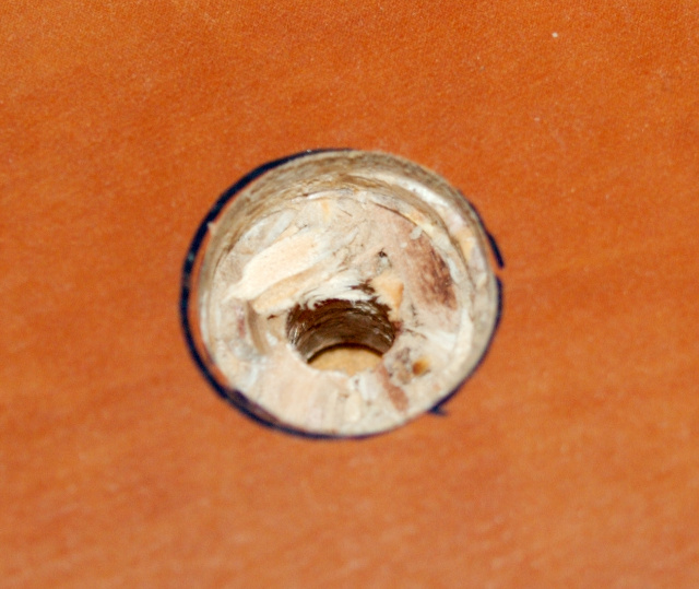
Since the laptop’s base is quite flat I needed to make the bolts attaching the
laptop platform to the main base flush with the surface. I did not have a
drill large enough to make a hole for the bolt heads so had to use a router to
enlarge the holes for a depth of about 3mm (this is why the large holes are a
little sloppy). These photos show the the mounting holes with and without a
bolt.
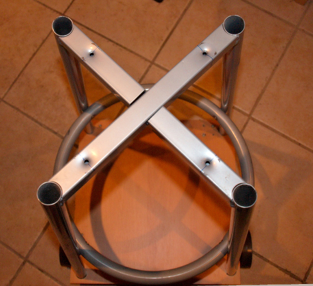
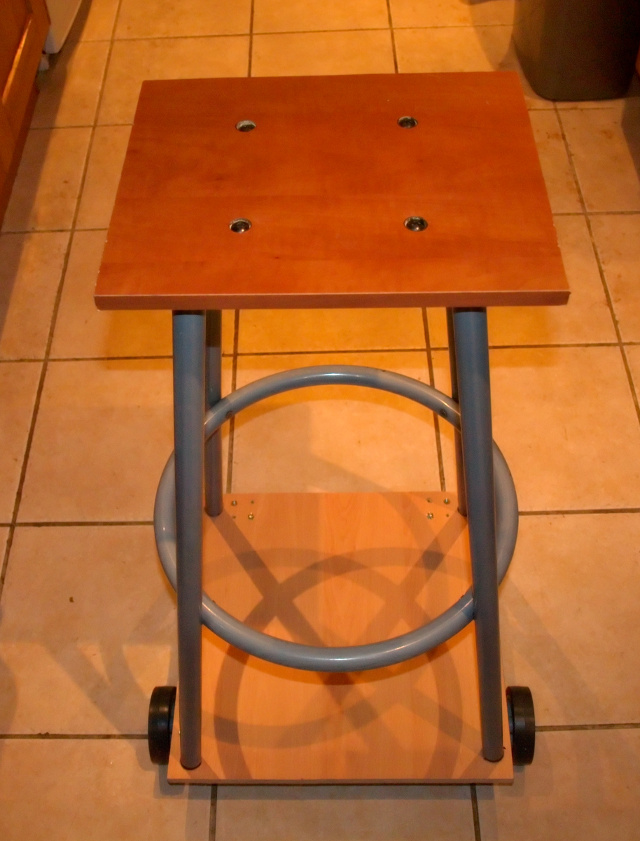
Top of the chair which handily already had drilled and tapped bolt holes
(originally used to attach the mounting bracket for the chair itself).
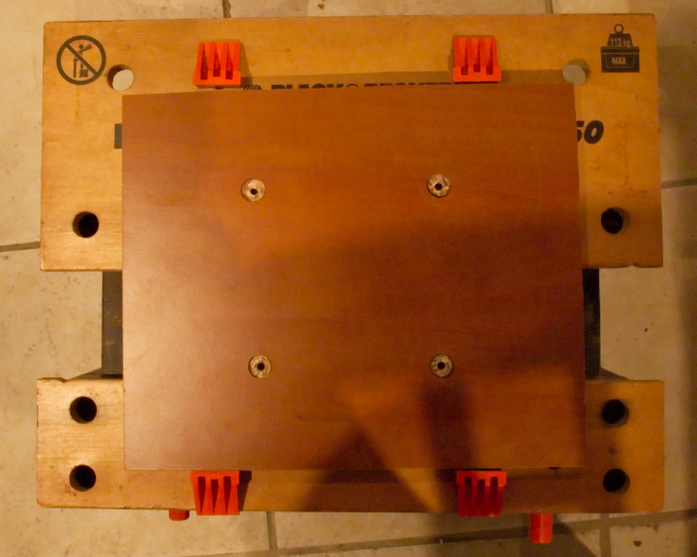
The completed robot platform without the laptop
So what we have at this point is a wheeled base with a platform for a laptop
on top. There are several advantages and disadvantages to this design.
Advantages
- The laptop is placed at the useful height off the ground and so we can make use of the display for interacting with people.
- The chair frame provides a strong mount for any additional hardware we might want to add later.
Disadvantages
- The result is quite heavy and the laptop is also heavy so the motors may struggle to move it and if they do it will quite likely be slow.